Crankcase Relief Valve
2023-06-23 16:41
Introduction
A crankcase explosion is caused by ignition of oil mist, itself created by the presence of a hot spot, which led to the evaporation of lubricating oil and its condensation into an oil mist. Its consequences can be severe, including death and serious injury to personnel and extensive damage to the engine.
SOLAS regulations to prevent crankcase explosions came into place after a particularly devastative explosion that claimed the lives of 28 people onboard MV Reina Del Pacifico in 1947.
Since then, many detection and preventive measures have been added to ships to eliminate or at least reduce the risk of this phenomenon. In this article, we shall take a look at what crankcase explosion is, how it occurs and what can be done to prevent it.
What Is a Crankcase Explosion on a Ship?
Crankcase explosion refers to the explosion that occurs in the crankcase of an engine due to the ignition of oil mist. A crankcase of an engine has all the necessary requirements for an explosion. We can understand it better with the help of a concept known as the fire triangle.
For any explosion/fire to occur, it needs three components. These are heat, fuel and oxygen and together, these three form what is known as the fire triangle.

However, oxygen and fuel need to exist in the right ratio for the fire to ignite. If it is either too lean (more oxygen, less fuel) or too rich (more fuel, less oxygen) it will not ignite.
This is why, even though the three components are always available in an engine crankcase, an explosion does not occur until the right air-fuel ratio is obtained. Let us take a look at the sequence of events that leads to a crankcase explosion.
How Does a Crankcase Explosion Occur?
As we have seen, a crankcase explosion requires three components: Heat, Oxygen and Fuel. Oxygen is always present in the crankcase through fresh air. Fuel in the case of crankcase explosion is lube oil vapor, and the necessary heat to ignite the air-fuel mixture is present when a hot spot develops.
Before we get to the sequence of events that lead to a crankcase explosion, we must understand what a hot spot is.
A hot spot is any region inside the crankcase of an engine that has an unusually high temperature due to some defect or damage. It can occur for a variety of reasons. Some leading causes of hot spot development are:
- Bearing failure
- Blow past
- Scavenge fire
- Overloaded engine
There are other causes too (crankshaft misalignment, poor quality lube oil, insufficient clearance, etc.) but they are not as common. When such conditions occur in the engine, they can cause local hot spots that have a temperature range between 200 to 400 degrees Celsius.
The flash point of the main engine crankcase lubricating oil is about 220 degrees Celsius. So when a hot spot occurs it first evaporates the surrounding oil into vapor. When this oil reaches relatively colder areas of the engine, it condenses and forms a white mist that is capable of explosion.
As this process continues and the air-fuel mixture present inside the crankcase reaches within a certain limit (known as the combustible range between LEL and UEL), a small explosion occurs initially. This explosion is known as the primary explosion.
The primary explosion sends a shock wave through the engine causing a sudden increase in the pressure inside the crankcase. This pressure may cause the development of cracks in the engine structure.
This is why we have crankcase relief valves fitted into the main engine. When the internal pressure of the crankcase increases between 0.2-1.0 bar, the valve lifts and relieves the pressure inside the crankcase. It also prevents the ingress of fresh air as it is a non-return valve.
However, leaky piston glands, cracks and other sources may reintroduce air and fuel into the crankcase which may result in a secondary explosion. The secondary explosion is far more severe than the primary explosion.
This explosion can result in a huge loss of property and is very likely to be fatal to the personnel around it. The ship crew must do everything in their power to prevent both types of explosions.
Crankcase explosion safety devices
Engine manufacturers have built many safety devices into marine diesel engines to prevent the occurrence of a crankcase explosion. These devices must be maintained well and observed diligently to detect the formation of hot spots and oil mist in a crankcase to prompt timely action.
Some of the common safety devices are:
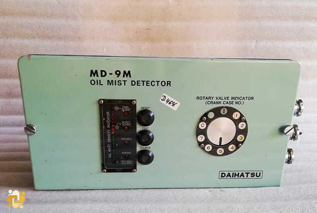
- Oil mist detector
- Crankcase relief valve
- Crankcase exhaust fan
- Breather pipe
- Lube oil temperature sensor
- Bearing temperature sensor
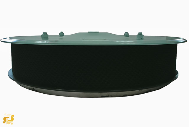
Crankcase relief valve
The relief valves built into the side of the crankcase prevent internal pressure build-up as well as fresh air ingress into the crankcase. It also prevents the exit of flame outside of engine by using a flame arrester. If a crankcase explosion occurs, the complete flame arrester must be replaced.
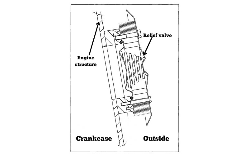
Fig. 2 - Crankcase relief valve in a Man B&W Diesel Engine
In the period 1998 to 2020, crankcase relief valves have undergone a safety-improving design development.
Functionality of crankcase explosion relief valves:
- Relieve the explosion pressure from the crankcase.
- Valves open
- Quenching the flame front with built-in flame arresters.
- Efficient flame arresters prevent fire and subsequent fire damage outside the crankcase.
- Furthermore, they prevent ignition of the oil mist cloud having escaped the crankcase.
- Close automatically after relieving the explosion pressure
- Air and gas tight valve closure constrains the amount of oxygen entering the crankcase after an explosion.
- Subsequently, the low oxygen concentration in the crankcase suppresses the crankcase fire and reduces the risk of subsequent explosions
The latest generation of crankcase explosion relief valves improves the protection of the crew and limits the damage if a crankcase explosion occurs.
In 2006 to 2020, four types of crankcase explosion relief valves have been type approved and meet the specifications in IACS UR M66, Type testing procedure for crankcase explosion relief valves. The makers and types of the approved relief valves are the following:
- Hoerbiger Ventilwerke, type EVX
- Halla Control Valves, type CR52
- Ziincheol Co. Ltd, type HWG (former name Hyunwoo SMT)
- Prosave, Type ERV (former name Unitech)
Fig. 3 shows a disassembled old-type crankcase explosion relief valve. The wire mesh in the picture will not function as a flame arrestor (keeping the flames from an explosion inside the engine). The picture on the left is from a situation where a crankcase explosion resulted in flame propagation into the engine room and a full-scale engine room fire.
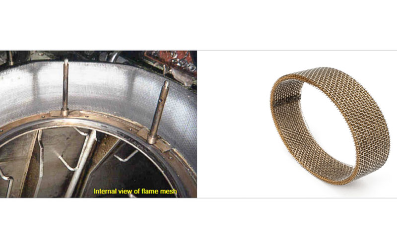
Fig.3: Old-type crankcase explosion relief valve
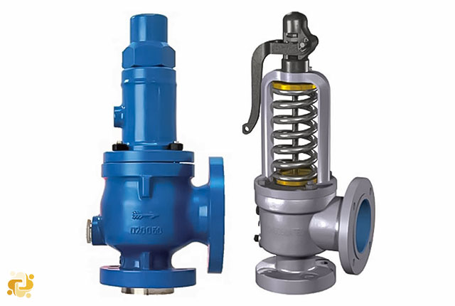
Fig. 4 shows two different modern crankcase explosion relief valves designed to withstand two explosions. Both types have been type-approved by IACS and MAN Energy Solutions.
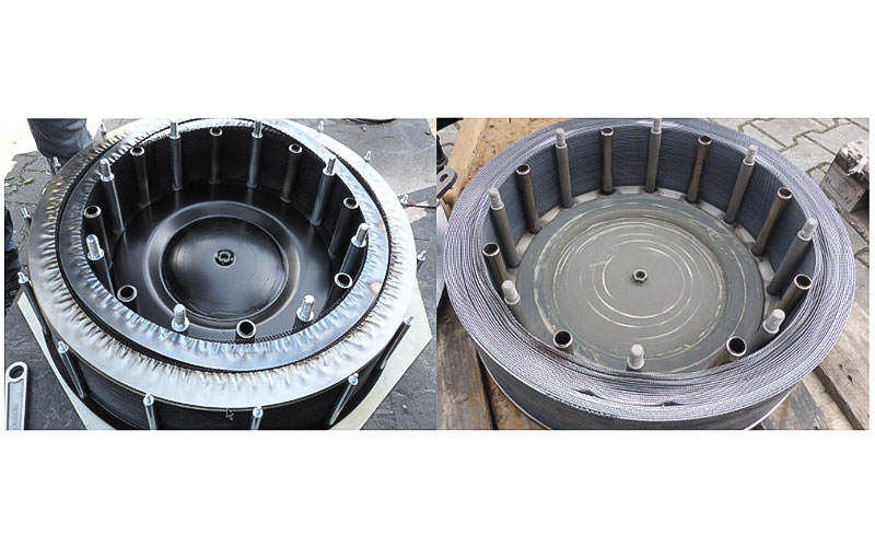
Fig. 4: Left: Hoerbiger EVX type. Right: Prosave ERV Type
These types of valves will relieve the explosion pressure from the crankcase while keeping the flames inside the engine, thereby preventing engine room fires.
Figs. 5 a/b/c show pictures taken in an engine room after a fire caused by a crankcase explosion. Actually, there were two explosions because the crankcase explosion relief valve did not close properly after the first explosion, causing fresh air to rush into the crankcase and creating a second explosion powerful enough to blow the crankcase doors off the engine.
IACS UR M66 type approved crankcase explosion relief valves will prevent this from happening.
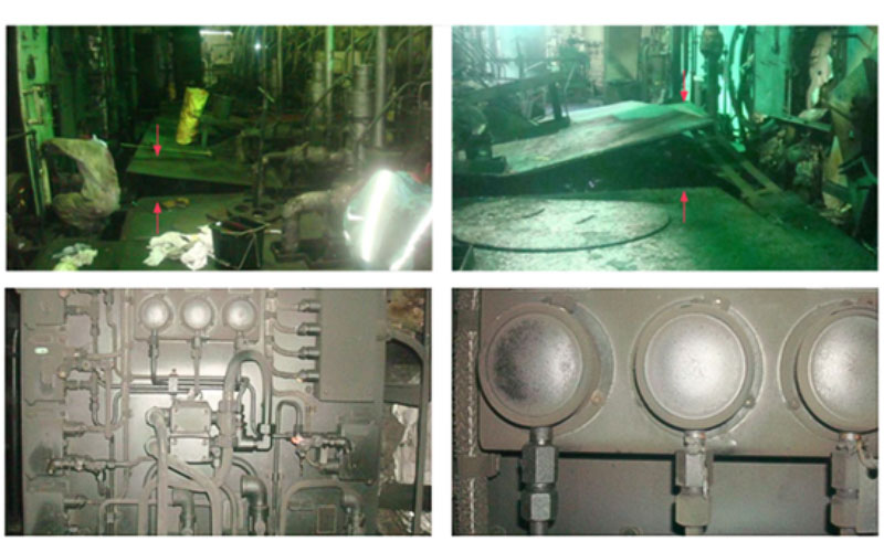
Fig. 5a: View from aft to fwd side
Fig. 5b: Left: control/safety air panel. Right: Close-up of control/safety air panel
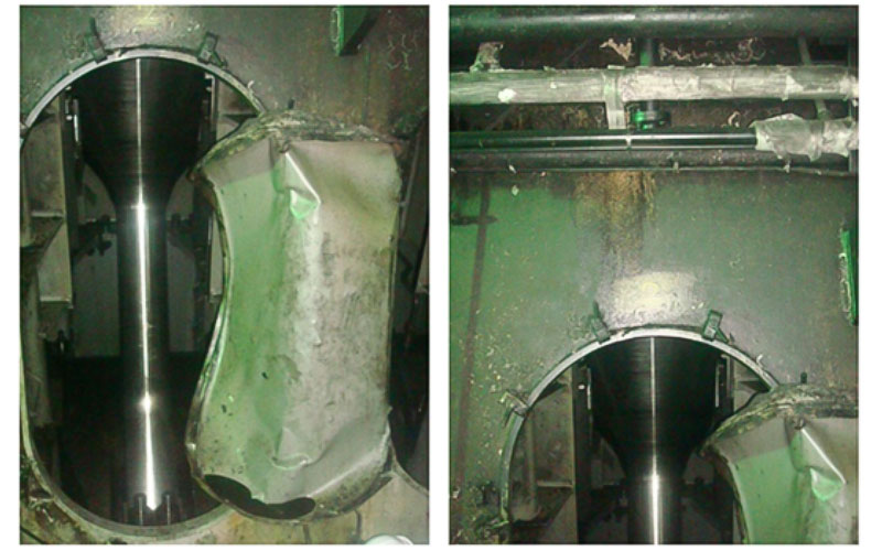
Fig. 5c: Left: crankcase unit #2. Right: above crankcase unit #2
IACS UR M9, Crankcase Explosion Relief Valves for Crankcases of Internal Combustion Engines
Internal combustion engines having a cylinder bore of 200 mm and above or a crankcase volume of 0.6 m3 and above shall be provided with crankcase explosion relief valves in accordance with this article.
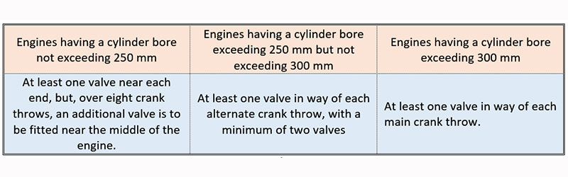
Table 1 – minimum requirement of explosion relief valves’ quantity
The free area of each relief valve is to be not less than 45 cm2.
The combined free area of the valves fitted on an engine must not be less than 115 cm2 per cubic meter of the crankcase gross volume.
Crankcase explosion relief valves are to be provided with lightweight spring-loaded valve discs or other quick-acting and self-closing devices to relieve a crankcase of pressure in the event of an internal explosion and to prevent the inrush of air thereafter.
The valve discs in crankcase explosion relief valves are to be made of ductile material capable of withstanding the shock of contact with stoppers at the full open position.
Crankcase explosion relief valves are to be designed and constructed to open quickly and be fully open at a pressure not greater than 0.02 N/mm2 (0.2bar).
Crankcase explosion relief valves are to be provided with a flame arrester that permits flow for crankcase pressure relief and prevents passage of flame following a crankcase explosion.
Crankcase explosion relief valves are to type tested in a configuration that represents the installation arrangements that will used on an engine in accordance with UR M66.
Where crankcase relief valves are provided with arrangements for shielding emissions from the valve following an explosion, the valve is to be type tested to demonstrate that the shielding does not adversely affect the operational effectiveness of the valve.
Crankcase explosion relief valves are to be provided with a copy manufacturer’s installation and maintenance manual that is pertinent to the size and type of valve being supplied for installation on a particular engine. The manual is to contain the following information:
- Description of valve with details of function and design limits
- Copy of type test certification
- Installation instructions
- Maintenance in service instructions to include testing and renewal of any sealing arrangements
- Actions required after a crankcase explosion
A copy of the installation and maintenance manual required by above is to be provided on board ship.
Plans of showing details and arrangements of crankcase explosion relief valves are to be submitted for approval in accordance with UR M44.
Valves are to be provided with suitable markings that include the following information:
- Name and address of manufacturer
- Designation and size
- Month/Year of manufacture
- Approved installation orientation
How to prevent crankcase explosion?
There are many tell-tale signs of an impending crankcase explosion which, when spotted on time, can help prevent it. Some of these signs require special instruments while others merely need careful observation.
The entire engine room crew must be familiar with these signs and symptoms for safe and incident-free operation of the main engine.
Crankcase explosion signs without any instruments:
- Check for hot spots with touch or infrared thermometer
- Irregular engine running
- Abnormal sound or vibration in the main engine
- Emergence of dense white mist or its smell from breather pipes or drain cocks
Crankcase explosion signs with instruments:
- Increase in bearing lube oil temperature
- Increase in bearing temperature
- Oil mist detector alarm
- Operation of crankcase relief valve and exit of smoke, sparks or oil
- Poor quality of crankcase lube oil
- Excessive clearances between mating parts such as piston/liner, piston rod/stuffing-box, engine bearings. etc.

Admin
Related Articles
Introduction to Pressure Safety Valve
2023-02-10 18:02
Oil Mist Detector
2022-09-06 12:09