Introduction to Inert Gas Systems (IGS)
2022-05-02 20:04
Introduction
Oil tankers carry oil of different grades and quality, having property to produce flammable vapors and gases when loaded for transportation. Even with no cargo on board, there can be harmful flammable gases present in the hold. When the vapor produced by an oil cargo is mixed with certain concentration of air primarily containing oxygen, it can result in explosion which results in damages to the property, marine pollution and loss of life. For safety against such explosion, Inert gas system is used on board. It can be through as a separate inert gas plant or flue gas produced by ship’s boiler.
Inert gas system is the most important integrated system for oil tankers for safe operation of the ship.
Inert gas is the gas which contains insufficient oxygen (normally less than 8 %) to suppress combustion of flammable hydrocarbon gases.
Inert gas system spreads the inert gas over the oil cargo hydrocarbon mixture which increases the lower explosion limit LEL (lower concentration at which the vapors can be ignited), simultaneously decreasing the Higher explosion limit HEL (Higher concentration at which vapor explodes). When the concentration reaches around 10 %, an atmosphere is created inside tank in which hydrocarbon vapors cannot burn. The concentration of inert gas is kept around 5% as a safety limit.
-a.jpg)
Application
With refer to the SOLAS 2014 Amend / Chapter II-2 / Reg. 4.5.5.1, the following vessel shall be fitted with the fixed inert gas system, as described below:
Tankers constructed before 1 September 1984
- Crude Oil Tankers: 20,000 DWT and upwards
- Tankers of 20,000 DWT and upwards and less than 40,000 DWT carrying oil other than crude oil fitted with tank washing machines having an individual throughout of greater than 60 m3/hr.
- Tankers other than crude oil tankers: 40,000 DWT and upwards
- All tankers operating with a cargo tank cleaning procedure using crude oil washing
Tankers constructed on or after 1 September 1984 ∼ 31 Dec. 2015
- 20,000 DWT and upwards
- All tankers operating with a cargo tank cleaning procedure using crude oil washing
Tankers constructed on or after 1 Jan. 2016
- 8,000 DWT and upwards
- Where liquid cargoes other than crude oil or petroleum products having a flashpoint not exceeding 60°C (closed cup test) or liquefied gases which introduce additional fire hazards are intended to be carried, additional safety measures shall be required, having due regard to the provisions of the International Bulk Chemical Code, as defined in regulation VII/8.1, the Bulk Chemical Code, the International Gas Carrier Code, as defined in regulation VII/11.1, and the Gas Carrier Code, as appropriate
- All tankers operating with a cargo tank cleaning procedure using crude oil washing
Tankers required to be fitted with inert gas systems shall comply with the following provisions:
- double-hull spaces shall be fitted with suitable connections for the supply of inert gas;
- where hull spaces are connected to a permanently fitted inert gas distribution system, means shall be provided to prevent hydrocarbon gases from the cargo tanks entering the double hull spaces through the system; and
- where such spaces are not permanently connected to an inert gas distribution system, appropriate means shall be provided to allow connection to the inert gas main.
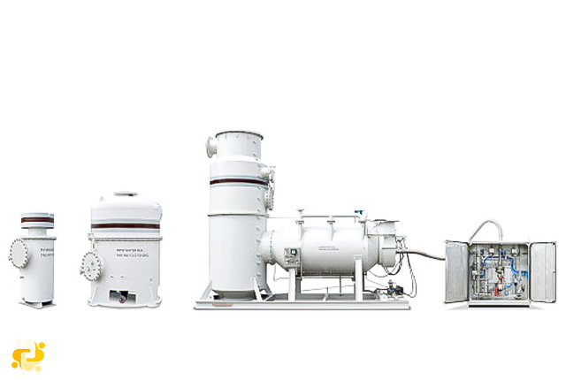
Components and description of IG system
The following components are used in a typical inert gas system in oil tankers:
- Exhaust gases source: inert gas source is taken from exhaust uptakes of boiler or main engine as contains flue gases in it.
- Inert gas isolating valve: It serve as the supply valve from uptake to the rest of the system isolating both the systems when not in use.
- Scrubbing tower: Flue gas enters the scrub tower from bottom and passes through a series of water spray and baffle plates to cool, clean and moist the gases. The SO2 level decreases up to 90% and gas becomes clear of soot.
- Demister: Normally made of polypropylene, it is used to absorb moisture and water from the treated flue gas.
- Gas Blower: Normally two types of fan blowers are used, a steam driven turbine blower for I.G operation and an electrically driven blower for topping up purpose.
- G pressure regulating valve: The pressure within the tanks varies with the property of oil and atmospheric condition. To control this variation and to avoid overheating of blower fan, a pressure regulator valve is attached after blower discharge which re-circulates the excess gas back to scrubbing tower.
- Deck seal: Purpose of the deck seal is to stop the gases to return back which are coming from the blower to cargo tanks. Normally wet type deck seals are used. A demister is fitted to absorb the moisture carried away by the gases.
- Mechanical non return valve: It is an additional non return mechanical device in-line with deck seal.
- Deck isolating valve: The engine room system can be isolated fully with the deck system with the help of this valve.
- Pressure Vacuum (PV) breaker: The PV breaker helps in controlling the over or under pressurization of cargo tanks. The PV breaker vent is fitted with flame trap to avoid fire to ignite when loading or discharging operation is going on when in port.
- Cargo tank isolating valves: A vessel has numbers of cargo holds and each hold is provided with an isolating valve. The valve controls the flow of inert gas to hold and is operated only by a responsible officer in the vessel.
- Mast riser: Mast riser is used to maintain a positive pressure of inert gas at the time of loading of cargo and during the loading time it is kept open to avoid pressurization of cargo tank
General requirements for inert gas systems
The inert gas system shall be capable of “inerting, purging and gas-freeing” empty tanks and maintaining the atmosphere in cargo tanks with the required oxygen content.
'Inerting ': means the introduction of inert gas into a tank with the object of attaining the inert condition.
'Gas-freeing ‘: means the introduction of fresh air into a tank with the object of removing toxic, flammable and inert gases and increasing the oxygen content to 21 per cent by volume.
'Purging' means the introduction of inert gas into a tank already in the inert condition with the object of:
- further reducing the existing oxygen content; and/or
- reducing the existing hydrocarbon gas content to a level below which combustion cannot be supported if air is subsequently introduced into the tank.
'Topping up ‘means the introduction of inert gas into a tank which is already in the inert condition with the object of raising the tank pressure to prevent any ingress of air.
In addition, Tankers fitted with a fixed inert gas system shall be provided with a closed ullage system.
Delivery Rate
- Delivering inert gas to the cargo tanks at a rate of at least 125% of the maximum rate of discharge capacity of the ship expressed as a volume. For chemical tankers and chemical/product tankers, the Administration may accept inert gas systems having a lower delivery capacity provided that the maximum rate of discharge of cargoes from cargo tanks being protected by the system is restricted to not more than 80% of the inert gas capacity; and
- Delivering inert gas with an oxygen content of not more than 5% by volume to the cargo tanks at any required rate of flow.
The inert gas supply may be:
- treated flue gas from main or auxiliary boilers, or
- gas from an oil or gas-fired gas generator, or
- gas from nitrogen generators.
The Administration may accept systems using inert gases from one or more separate gas generators or other sources or any combination thereof, provided that an equivalent level of safety is achieved. Such systems shall, as far as practicable, comply with the requirements of this chapter. Systems using stored carbon dioxide shall not be permitted unless the Administration is satisfied that the risk of ignition from generation of static electricity by the system itself is minimized.
Safety measures
- The inert gas system shall be so designed that the maximum pressure which it can exert on any cargo tank will not exceed the test pressure of any cargo tank.
- Automatic shutdown of the inert gas system and its components parts shall be arranged on predetermined limits being reached.
- Suitable shutoff arrangements shall be provided on the discharge outlet of each generator plant.
- Arrangements shall be provided to enable the functioning of the inert gas plant to be stabilized before commencing cargo discharge. If blowers are to be used for gas-freeing, their air inlets shall be provided with blanking arrangements.
- Where a double block and bleed valve is installed, the system shall ensure upon of loss of power, the block valves are automatically closed and the bleed valve is automatically open.

Admin
Related Articles
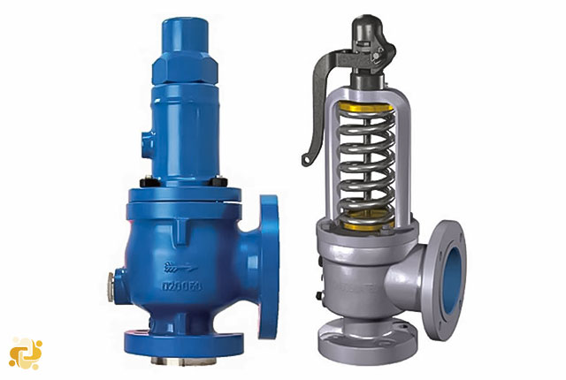
Introduction to Pressure Safety Valve
2023-02-10 18:02
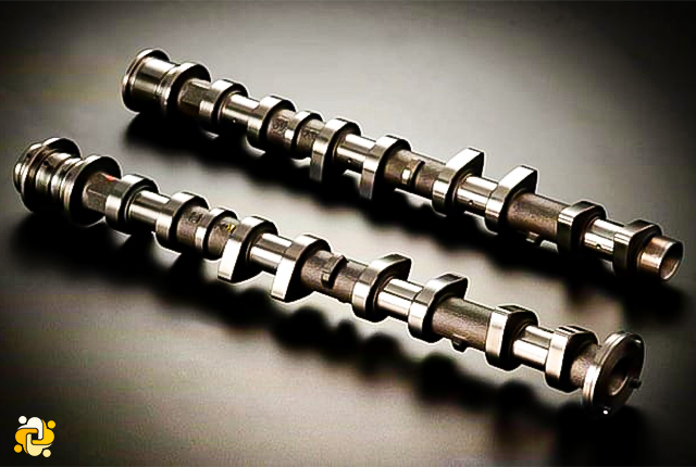
Camshaft less Engines
2022-05-05 18:05

Plate Type Heat Exchangers
2023-09-09 10:09
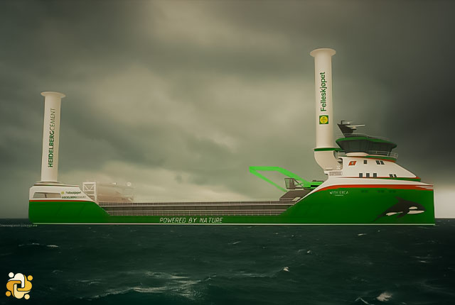
The wind propulsion technology
2023-09-13 13:09