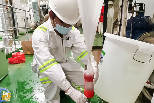
Sampling point in the ballast water discharge line
2023-12-23 14:37
Introduction
In accordance with article 9 of the Convention, a Party may sample the ship’s ballast water for the purpose of determining whether the ship is in compliance with the Convention in accordance with these Guidelines.
Article 9 Inspection of Ships: A ship to which this Convention applies may, in any port or offshore terminal of another Party, be subject to inspection by officers duly authorized by that Party for the purpose of determining whether the ship is in compliance with this Convention. Except as provided in paragraph 2 of this Article, any such inspection is limited to:
- verifying that there is onboard a valid Certificate, which, if valid shall be accepted; and
- inspection of the Ballast Water record book, and/or
- a sampling of the ship's Ballast Water, carried out in accordance with the guidelines to be developed by the Organization. However, the time required to analyze the samples shall not be used as a basis for unduly delaying the operation, movement or departure of the ship.
Sampling requirements for compliance control of regulations D-1 and D-2 of the Convention will differ as these two regulations have significantly different parameters. Regulation D-1 is no longer allowed on ships except for very special situations. Therefore, sampling to control compliance with this standard is not very practical anymore.
Regulation D-2 of the Convention refers to two size categories of organisms and a group of indicator microbes. Ships conducting ballast water management in accordance with regulation D-2 shall discharge:
- less than 10 viable organisms per cubic meter greater than or equal to 50 micrometers in minimum dimension;
- less than 10 viable organisms per milliliter less than 50 micrometers in minimum dimension and greater than or equal to 10 micrometers in minimum dimension; and
- discharge of the indicator microbes shall not exceed:
- Toxicogenic Vibrio cholera (O1 and O139) with less than 1 colony forming unit (cfu) per 100 milliliters or less than 1 cfu per 1 gram (wet weight) zooplankton samples;
- Escherichia coli less than 250 cfu per 100 milliliters; and
- Intestinal Enterococci less than 100 cfu per 100 milliliters.
Although the Convention contains no requirements for provision of sampling points, the Guidelines for approval of ballast water management systems (G8) adopted by resolution MEPC.174(58) do expressly call for the provision of sampling facilities, not only for the purpose of type approval, but also for the purpose of other required sampling process. As a result, the existence of sampling points as mentioned in this article will be necessary.
What is the “Sampling Point”?
“Sampling Point” means that place in the ballast water piping where the sample is taken. Samples should be taken from the discharge line, as near to the point of discharge as practicable, during ballast water discharge whenever possible. Sampling via manholes, sounding pipes, or air pipes is not the preferred approach for assessing compliance with regulation D-2. Scientific trials have shown that using these sampling locations may not provide accurate estimates of organism concentrations that would occur in the discharge, i.e. such sampling may provide an under- or over-estimate of the concentration of organisms.
In-tank sampling should only be used if ballast water treatment occurs on uptake prior to or whilst ballast water is in the tank. If any part of the treatment process occurs during the ballast water discharge, then in-tank sampling will be inappropriate. In light of these potential shortcomings, sampling to determine compliance with regulation D-2 should, whenever practicable to do so, be carried out in the discharge line near the discharge point. An exception to this is the case when tanks are emptied through direct overboard discharge valves, as in upper side wing tanks, rather than through the ballast pumps. In such cases, tank sampling may be an appropriate approach. Of course, it should be noted that in this case, it is necessary to choose proper BWTS according to the requirements.
Sampling from the ballast water discharge line
In order to undertake an accurate measurement on the organism concentration in the ballast water, it is recommended to install an “isokinetic” sampling facility. Isokinetic sampling is intended for the sampling of water mixtures with secondary immiscible phases (i.e. sand or oil) in which there are substantial density differentials. In such conditions, convergence and divergence from sampling ports is of significant concern. Since most organisms are relatively neutrally buoyant, true isokinetic sampling is unnecessary. However, the mathematics related to isokinetic sampling are deemed to be useful as a basis for describing and specifying sampling geometries. Isokinetic sampling is necessary to ensure that a sample contains the same proportions of the various flowing constituents as the flow stream being sampled. During isokinetic sampling the sampling device does not alter the profile or velocity of the flowing stream at the moment or point at which the sample is separated from the main flow stream. Under isokinetic conditions, the velocities of both the sample and the main flow are equal at the point at which the sample is separated from the main flow. To achieve isokinetic sampling conditions, a sampler is designed to separate a subsection of the total flow-stream in a manner that does not encourage or discourage water entry other than that which is otherwise in the cross-section of the sampler opening. In other words, flow streams in the main flow of the pipe should not diverge or converge as they approach the opening of the sampler.
Technical specifications for design of in-line sampling facilities
Through computational fluid dynamics modelling, it has been shown that the isokinetic diameter calculation can provide guidance for sizing of sample ports for sampling of organisms. Simulations showed that flow transitions from the main stream were best for sample port diameters between 1.5 and 2.0 times the isokinetic diameter. Ports sized in this range had smooth transitions and pressure profiles that allowed for direct sampling without the need of a pump to induce sample collection. The isokinetic sample port diameter should therefore be determined generally according to the equation:
Diso = Dm √ (Qiso / Qm)
where Diso and Dm are the diameters of the sample port opening and the main flow in the discharge line, respectively; and Qiso and Qm represent the respective volumetric flow rates through the two pipes. It is recommended that sample port size be based on the combination of maximum sample flow rate and minimum ballast flow rate that yields the largest isokinetic diameter.
The opening of the sampling pipe should be chamfered to provide a smooth and gradual transition between the inside and outside pipe diameters. The length of the straight sample pipe facing into the flow can vary, but should not usually be less than one diameter of the sampling pipe. The sampling port should be oriented such that the opening is facing upstream and its lead length is parallel to the direction of flow and concentric to the discharge pipe which may require sampling pipes to be “L” shaped with an upstream facing leg if installed along a straight section of discharge pipe.
The need to be able to service the sample pipe is important and should be considered, taking the safety of ship into consideration. Therefore, the sampling pipe should be retrievable either manually, or mechanically, or it should be in a system which can be isolated. Because of the potential for the opening and interior of the sample pipe to become occluded by biological or inorganic fouling, it is recommended that samplers be designed to be closable at the opening, removed between sampling intervals or be easily cleaned prior to sampling.
The sample pipe and all associated parts of the sampler that come into contact or near proximity with the ballast piping should be constructed of galvanically compatible materials and generally corrosion resistant. Any corrosion of the sampling system will affect sample flow rates and potentially sample representativeness.
If flow control of the sample flow rate is required, ball, gate and butterfly valve types should be avoided as they may cause significant shear forces which may result in organism mortality. For flow control, it is recommended that diaphragm valves or similar valve types be used to minimize sharp velocity transitions. For flow distribution, ball valves may be utilized in such a manner that they are either fully open or fully closed.

Admin
Related Articles

Ballast Water Management Convention
2022-06-14 15:06

Commissioning Testing of Ballast Water Management System
2022-06-23 11:06
Guidance on ballast water record-keeping and reporting
2023-08-26 11:08
Fuel oil sampling and verification
2022-04-19 21:04