The Science of Ship Propellers: From Basics to Future Innovations
2023-10-02 07:57
Introduction
In the world of maritime engineering, propellers play a pivotal role in propelling vessels through water, making them a cornerstone of ship propulsion. This technical article explores the fundamental principles of propellers, delves into various types of propellers, their materials and construction, and provides insights into future innovations in ship propulsion technology.
History
John Ericsson, hailing from the Swedish province of Vermland, can be credited as the inventor of the ship propeller. This groundbreaking invention found its way into the design of the iconic Civil War ironclad vessel, the Monitor.
Ericsson's journey into the realm of engineering began when he initially contributed to the planning of a Swedish canal. During his involvement with this project, he received tutelage in mathematics and the sciences, further fueling his passion for innovation. His dedication led him to enlist in the Swedish Army at the tender age of 17, where he engaged in topographical surveying.
In 1826, Ericsson embarked on a transformative chapter in London, showcasing the breadth of his engineering prowess. His achievements included advancements in power transmission through compressed air, pioneering new steam boiler designs, introducing condensers to enhance the range of marine steam engines, and developing engines for warships positioned below the waterline, offering protection against shellfire. His contributions extended to creating the steam fire-engine, a steam locomotive, and a device capable of extracting salt from brine, and pioneering superheated steam engines and the "caloric" engine.
Among his myriad inventions, Ericsson's most enduring legacy remains the screw propeller, a propulsion system that remains a cornerstone of maritime engineering. In 1839, he introduced propellers to vessels navigating canals and inland waterways, marking a significant milestone in marine technology.
Notably, Ericsson's innovative spirit extended to the construction of a formidable "big frigate" for the U.S. Navy, underscoring his dedication to advancing naval technology. His crowning achievement in naval engineering came with the design and construction of the Monitor, a vessel that played a pivotal role in the Union Navy during the Civil War. Impressively, he accomplished this feat within a mere 100 working days, solidifying his status as a pioneering figure in the annals of maritime history.

Figure 1 - John Ericsson
What is a propeller?
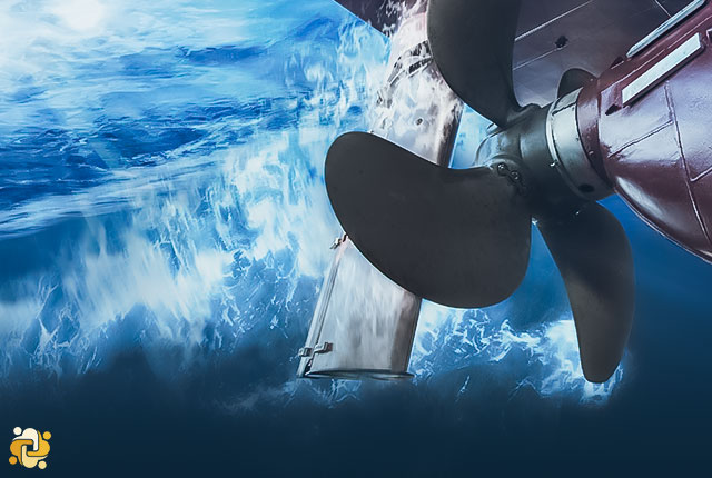
A ship propeller, often simply referred to as a propeller, is a crucial component of a ship's propulsion system. It is a rotating device with a set of blades that are strategically designed to generate thrust and propel the ship through water. Ship propellers are typically located at the stern (back) of the vessel and are immersed in the water.
The primary function of a ship propeller is to convert the mechanical power generated by the ship's engines into a forward or backward motion by pushing or pulling water. This action creates a reaction force in the opposite direction, adhering to Newton's third law of motion, which states that for every action, there is an equal and opposite reaction.
Material and Construction of Propeller
Marine propellers are made from corrosion-resistant materials as they are made operational directly in seawater which is a corrosion accelerator. The materials used for making marine propellers are an alloy of aluminum and stainless steel. Other popular materials used are alloys of nickel, aluminum, copper alloy castings and bronze which are 10-15 % lighter than other materials and have higher strength.
Propeller castings are classified as specified in below:
- High strength brass casting, Grade 1, CU 1
- High strength brass casting, Grade 2, CU 2
- Aluminum bronze casting, Grade 3, CU 3
- Aluminum bronze casting, Grade 4, CU 4
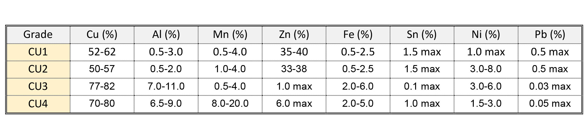
Table 1 – Chemical Composition of propeller castings, Classification rules
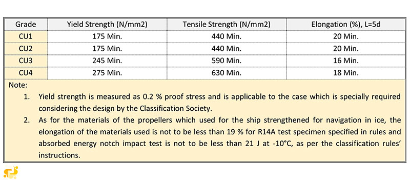
Table 2 – Mechanical Properties of Propeller Castings, Classification Rules
Types of Propellers
Propellers are be classified on the basis of several factors. The classification of different types of propellers is shown below:
Classification by Number of Blades Attached
Propeller blades come in various configurations, ranging from three blades to four blades, and sometimes even five blades. However, the most commonly used options are three-blade and four-blade propellers.
A three-blade propeller exhibits the following characteristics:
- It boasts a lower manufacturing cost compared to other types.
- Typically, it is constructed from aluminum alloy materials.
- Offers excellent high-speed performance.
- Provides superior acceleration when compared to other designs.
- However, it may not be as efficient for low-speed handling.
A four-blade propeller, on the other hand, demonstrates the following features:
- Its manufacturing cost is generally higher than that of three-blade propellers.
- Typically crafted from stainless steel alloys for enhanced strength and durability.
- Delivers commendable low-speed handling and overall performance.
- Exhibits better holding power in rough seas.
- Offers improved fuel economy compared to other propeller types.
In the case of a five-blade propeller, these characteristics are notable:
- The manufacturing cost is higher than all other propeller types.
- It tends to produce minimal vibrations compared to other configurations.
- Five-blade propellers excel in providing substantial holding power in rough sea conditions.
Finally, the six-blade propeller possesses the following attributes:
- It is associated with a high manufacturing cost.
- Similar to the five-blade design, it generates minimal vibrations.
- Six-blade propellers are known for their remarkable holding power in rough seas.
- They exhibit a reduced induced pressure field over the propeller.
- Large container ships are often equipped with five or six-bladed propellers for their enhanced performance in challenging maritime conditions.
Classification By pitch of the blade
Pitch of a propeller can be defined as the displacement that a propeller makes for every full revolution of 360 ̊. The classification of the propellers on the basis of pitch is as follows:
Fixed Pitch Propeller
The blades in the fixed pitch propeller are permanently attached to the hub. The fixed pitch type propellers are cast and the position of the blades and hence the position of the pitch is permanently fixed and cannot be changed during the operation. They are normally made from copper alloy.
Fixed pitch propellers are robust and reliable as the system doesn’t incorporate any mechanical and hydraulic connection as in Controlled Pitch Propeller (CPP). The manufacturing, installation and operational costs are lower than the controlled pitch propeller (CPP) type. The maneuverability of the fixed-pitch propeller is also not as good as CPP.
These types of propellers are fitted in a ship that does not have good maneuverability requirements.
Controllable Pitch Propeller
In a Controlled Pitch type propeller, it is possible to alter the pitch by rotating the blade about its vertical axis by means of mechanical and hydraulic arrangement. This helps in driving the propulsion machinery at constant load with no reversing mechanism required as the pitch can be altered to match the required operating condition. Thus the maneuverability improves and the engine efficiency also increases.
This drawback includes the possibility of oil pollution as the hydraulic oil in the boss which is used for controlling the pitch may leak out. It is a complex and expensive system from both installation and operational points. Moreover, the pitch can get stuck in one position, making it difficult to maneuver the engine.
However, the propeller efficiency for the CP propeller is slightly lower than the same size FP propeller due to the larger hub to accommodate the blade pitch mechanism and piping.
Installation tests of new ships’ propellers
When it comes to the installation of new ship propellers, a series of rigorous tests and inspections are essential to ensure their optimal performance and safety. Here, we delve into these crucial installation tests in more detail:
Balancing Tests
One of the fundamental aspects of propeller installation is the meticulous examination of its balance. Propellers must undergo both static and dynamic balancing tests to ascertain their stability and precision.
Static Balancing Tests: These tests are conducted to evaluate the propeller's balance while it remains stationary. Ensuring that the propeller is perfectly balanced when not in motion is critical for avoiding vibrations and undue stress on the propulsion system. Any imbalances discovered during static balancing tests are addressed promptly to prevent issues during operation.
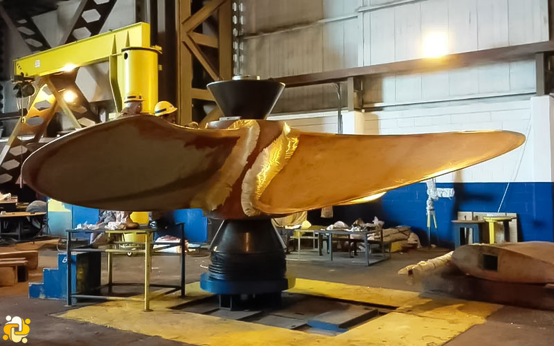
Figure 2 - Static Balancing Test
- Dynamic Balancing Tests: Dynamic balancing tests are particularly vital for propellers that will operate at speeds exceeding 500 revolutions per minute (rpm). These tests assess the propeller's balance while it is in motion, mimicking real-world conditions. They help identify any dynamic imbalances that might occur during operation, which can lead to vibrations and potential damage to the vessel. If issues are detected, corrective measures are taken to rectify them.
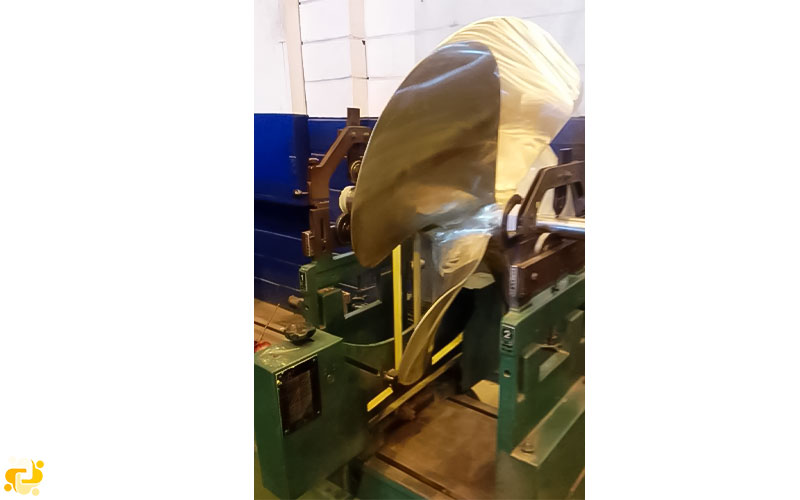
Figure 3 - Dynamic Balancing Test
Contact Tests
In cases where the propeller is force-fitted onto the taper of the propeller shaft cone, it is imperative to conduct contact tests. These tests focus on verifying the precise alignment and contact points between the propeller and the mating surfaces, such as the shaft cone. This meticulous examination ensures that the propeller is securely attached, minimizing the risk of slippage or misalignment during operation. Various methods, including contact-facing tests and other suitable means, are employed to assess the contact between these critical components.
Confirmation of Push-Up Length
For propellers that are force-fitted onto the propeller shaft without the use of a key, it is essential to confirm and record the push-up length. This parameter indicates the depth to which the propeller is fitted onto the shaft. Ensuring the correct push-up length is crucial for maintaining the propeller's optimal position and alignment. Any deviations from the specified push-up length can lead to inefficiencies, vibrations, or even damage to the propulsion system. Therefore, accurate measurement and documentation of this parameter are integral to the installation process.
A look to the future
By 2030, the marine industry is expected to see significant advancements in ship propulsion technology. One area of focus will be on reducing emissions and improving fuel efficiency. This will likely lead to the development of hybrid propulsion systems that combine traditional propellers with electric motors or alternative fuels.
Another area of focus will be on improving the maneuverability and speed of vessels. This could lead to the development of new types of propulsion systems, such as magneto hydrodynamic propulsion or air lubrication systems.
Additionally, there may be advancements in materials science that allow for the creation of more efficient and durable propellers. This could include the use of composite materials or 3D printing technology.
Overall, the future of ship propellers will likely see a combination of traditional and innovative technologies that prioritize efficiency, sustainability, and performance.
Three Innovative Propeller Types
Sharrow Propeller
The Sharrow Propeller is an innovative marine propulsion technology designed to enhance efficiency and reduce fuel consumption. Invented by Dr. James Sharrow and developed by Sharrow Marine over seven years, it features a unique blade design that reduces drag, increases thrust, and can lower fuel consumption by up to 15% compared to traditional propellers. This groundbreaking technology also offers improved vessel performance, quieter operation, and reduced emissions, making it environmentally sustainable. However, potential drawbacks include its initial cost, limited availability, ongoing testing for long-term durability, and compatibility concerns with certain vessels and engines. Despite these challenges, the Sharrow Propeller represents a significant advancement in marine propulsion technology and is likely to gain popularity in various marine applications.
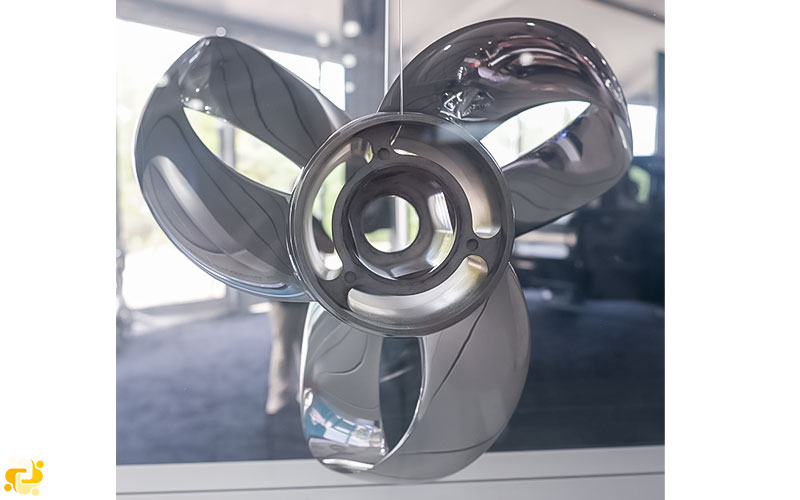
Figure 4 - The Sharrow Propeller
How it works?
The Sharrow Propeller represents a groundbreaking advancement in marine propulsion technology. Unlike a standard propeller, which generates a concentrated tip vortex leading to energy loss and the risk of cavitation, the Sharrow Propeller eliminates this problem entirely by design. The key innovation lies in the absence of a traditional propeller tip, which means there is no corresponding tip vortex. This distinctive feature has been empirically validated through underwater video footage comparing the performance of a conventional propeller to that of the Sharrow Propeller.
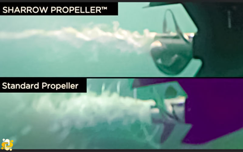
Figure 5 - Sharrow Propeller VS. Standard Propeller
In these captivating underwater visuals, the contrast between the two propeller types becomes strikingly apparent. When observing the conventional propeller in action, it becomes evident that the "bubbles" emanating from each blade converge into the familiar helical patterns, unmistakably indicating the presence of the tip vortex. It is noteworthy that the occurrence of tip vortex cavitation (TVC) is not solely a function of tip speed but is more intricately related to blade loading.
In stark contrast, the Sharrow Propeller™ showcases a mesmerizing absence of tip vortex cavitation when viewed through the lens of the underwater video. This remarkable outcome underscores the Sharrow Propeller's unparalleled ability to mitigate energy loss and cavitation, setting a new standard in marine propulsion technology. Its innovative design, characterized by the elimination of the traditional propeller tip and its consequential eradication of the tip vortex, represents a transformative leap forward in the world of marine engineering.
Electromagnetic thrusters
Electromagnetic forces potentially provide a means of propulsion for a ship without the aid of propellers or oars. The laws governing the electromagnetic force were known in the 19th century, apart from a few isolated experiments such as Faraday's attempt to measure the voltage along the River Thames caused by Its movement through the Earth's magnetic field and Hartmann's work on electromagnetic pumps in Measured in 1918, the subject largely awaited engineering development until the 1960s.
The idea of electromagnetic thrusters was first patented in the United States by Rice during 1961. After this invention, the United States took an important role in theoretical and experimental studies, which led to the Westinghouse Research Laboratory report in 1966. The report suggests that higher magnetic field densities are needed before this option can provide a real alternative to ship propulsion. In the 1970s, superconducting coils allowed for further advances in this concept.
The basic principle of electromagnetic propulsion is based on the interaction of the magnetic field B, which is placed by a fixed coil inside the ship, and the electric current passed through the seawater from the electrodes on the bottom of the ship or through a conduit, as shown diagrammatically is shown, is created. In the figure below, since the magnetic field and the current are in orthogonal directions, the resulting Lorentz force provides the necessary pumping action. The Lorentz force is J × B, where J is the induced current density.
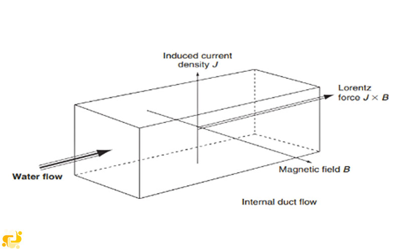
Figure 7
In this case, the electric field can be created internally or externally by placing a system of electrodes on the bottom of the ship. However, this method is relatively inefficient for ship propulsion. Most work has focused on systems using internal magnetic fields, and the principle of this type of system is shown in Figure a, where a channel, through which seawater flows, is surrounded by superconducting magnetic coils immersed in a cryostat. . Inside the tube there are two electrodes that create the electric field necessary to interact with the magnetic field in order to create the Lorentz force necessary for propulsion. This issue is due to the low conductivity of sea water, which is one of the losses on this unit. The efficiency in terms of load speed is proportional to the square of the magnetic flux intensity and the current speed ratio, which is a function of the float speed.
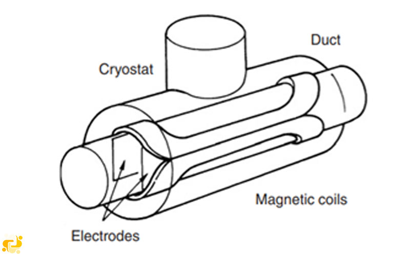
Figure 8
Electromagnetic propulsion has certain potential advantages in terms of providing a basis for noise- and vibration-free hydrodynamic propulsion.
However, a major obstacle to the development of electromagnetic force until the last few years was that the superconducting coil, in order to maintain its zero resistance property, must be kept at the temperature of liquid helium, 4.2 K (-268°). This clearly requires the use of thermally insulated vessels in which the superconducting coil can be placed to maintain these conditions. The criticality of this thermal condition can be seen from the figure below, which shows how the resistance of a superconductor changes with temperature and eventually reaches a critical temperature. Superconductors are also sensitive to current and magnetic fields, which if too high, the superconductor it will be ruined.
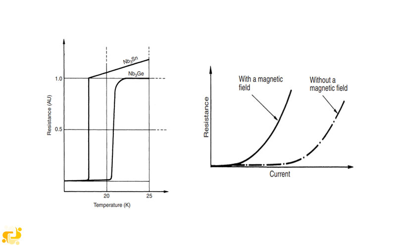
Figure 9
Superconductivity began with the work of Kamerlingh Onnes at Leiden University in 1911, when he discovered the superconductivity of mercury in liquid helium. For this he won the Nobel Prize. Work on superconductivity continued, however, progress was slow in finding metals that would function at the high temperature of liquid nitrogen, -196°C. Until 1973, the best achievable temperature was 23 degrees Kelvin. However, in 1986 Müller and Bednorz in Zurich turned their attention to ceramic oxides, which until now were considered insulators. The result of this change was an immediate increase of the critical temperature to 35 degrees Kelvin using a combination of lanthanum, barium, and copper oxide. This discovery made Muller and Bednors also receive the Nobel Prize for their work. As a result of this discovery, work intensified in the United States of America, China, India and Japan.
While these developments are clearly encouraging because they make it easier to use superconducting coils in terms of thermal insulation, many ceramic oxides are relatively difficult to manufacture. Firstly, the process by which the superconductor is made is very important if we want to get the correct molecular structure, and secondly, ceramics are fragile. Consequently, while this form of propulsion clearly has potential and significant progress has been made in both basic research and application, much work remains to be done before this type of propulsion can be implemented on a commercial or even conceptual scale.

Admin
Related Articles
Common Problems in Steering Gear System
2022-05-05 18:05
Introduction to Inert Gas Systems (IGS)
2022-05-02 20:05
Understanding UMA (UMS) Ships and Their Operational Requirements
2023-10-18 17:10

Anchor Windlass Design and Testing (IACS 2018 Requirement)
2023-11-15 08:11