Understanding Air Pipes on Ships and Load Line Convention Requirements
2023-10-10 08:00
Air Pipes
When you start filling a tank with liquid, the liquid displaces the air inside. As the liquid level rises, it compresses the air until the air pressure inside matches the pressure of the liquid. At this point, further filling is halted because the air pressure needs to be released to continue filling. To ensure that the air pressure inside these compartments and tanks remains the same as the atmospheric pressure outside, air pipes are installed. These pipes run from the ceiling of the tank or compartment to the outside environment. They allow air to flow freely, preventing pressure build-up or vacuum formation inside. This ensures that the pressure inside the tank or compartment is always in equilibrium with the atmospheric pressure. The upper ends of these air pipes are equipped with specific fittings to prevent unintentional flooding during adverse weather conditions. This is important for maintaining the integrity and safety of the ship.
Notably, the term "Air pipe" is not used in the context of cargo compartments. This indicates that cargo compartments have different ventilation or pressure management systems, which are not discussed in this text.
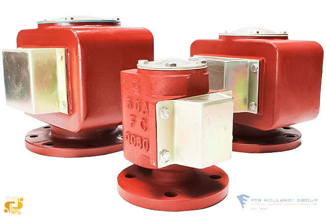
Where air pipes to ballast and other tanks extend above the freeboard or superstructure decks, the exposed parts of the pipes shall be of substantial construction; the height from the deck to the point where water may have access below shall be at least 760 mm on the freeboard deck and 450 mm on the superstructure deck. Where these heights may interfere with the working of the ship, a lower height may be approved, provided that the Administration is satisfied that the closing arrangements and other circumstances justify a lower height. Air pipes shall be provided with automatic closing devices In ships, the typical categories of air pipes can be classified as Bonnet Type and Goose Neck Type.
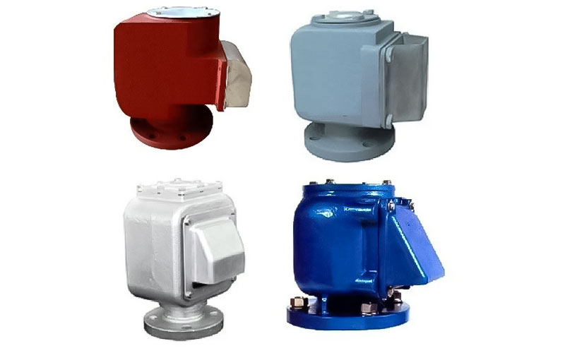
The measurement of the above mentioned height of bonnet type air pipes is calculated from the place of installation to the place where water can penetrate the air path of the pipe. If the cap is opened, this place is easily visible. In the case of Goose Neck type air pipes, the height to the lowest curved part of the pipe shape is considered.
The height of air pipes may be required to be increased on ships of Type ‘A’, Type ‘B-100’ and Type ‘B-60’ where this is shown to be necessary by the floatability calculations required by the Load Lines, 1966/1988 - International Convention on Load Lines, 1966, as Amended by the Protocol of 1988. An increase in height may also be required or recommended by individual Administrations when air pipes to fuel oil and settling tanks are situated in positions where sea-water could be temporarily entrapped, e.g. in recesses in the sides and ends of superstructures or deckhouses, between hatch ends, behind high sections of bulwark, etc.
Where air pipes are led through the side of superstructures, the opening is to be at least 2, 3 m above the summer load waterline. Where permitted by the National Authority, air pipe coaming heights may be reduced on ships engaged on protected or extended protected water service. Coaming heights are to be as high as practicable, with a minimum height of 450 mm.
Minimum wall thickness of pipes (applicable to ICLL Regulations 19, 20 and 22)
For air pipes in position 1 and 2 leading to spaces below the freeboard deck or to spaces within enclosed superstructures:
- External diameter of pipes equal to or less than 80 mm: thickness not less than 6,0 mm
- External diameter of pipes equal to or more than 165 mm: thickness not less than 8,5 mm
- Other external diameters: Intermediate sizes are to be determined by linear interpolation.
For air pipes other than specified above:
- External diameter of pipes equal to or less than 155 mm: thickness not less than 4,5 mm
- External diameter of pipes equal to or more than 230 mm: thickness not less than 6,0 mm
- Other external diameters: Intermediate sizes are to be determined by linear interpolation
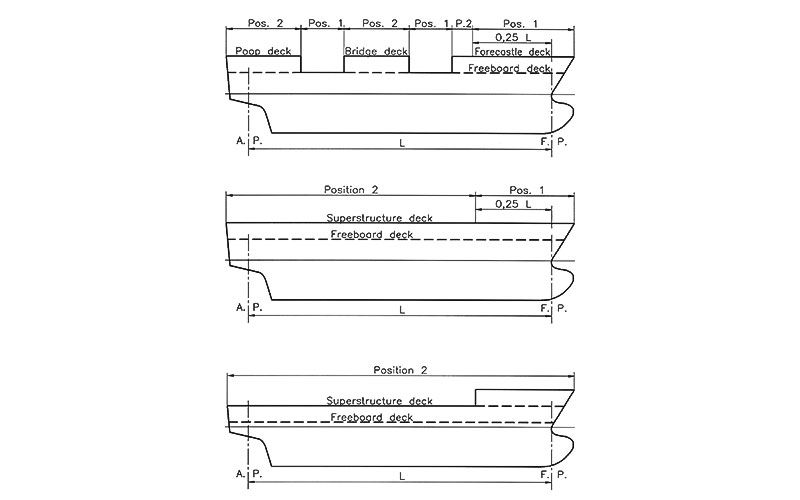
Positions 1 and 2
To simplify this, imagine a point located one-quarter of the freeboard length (Lf) aft of the forward perpendicular (FP). Positions 1 and 2 are ascertained based on the deck's elevation in relation to this point.
When considering the area forward of this point, if the height of the desired deck—whether it's the freeboard deck, superstructure deck, or other exposed decks—is less than twice the standard superstructure height, it corresponds to position 1. Conversely, if the desired deck's height equals or exceeds twice the standard superstructure height, it corresponds to position 2.
In the aft section of this designated point, if the desired deck's height is less than the standard superstructure height, it is categorized as position 1; otherwise, it falls under position 2. It's crucial to emphasize that the calculation and precise determination of the standard superstructure height adhere to the specifications outlined in the Load Line Convention.

Admin
Related Articles
Sampling point in the ballast water discharge line
2023-12-23 14:12

The Engine International Air Pollution Prevention Certificate (EIAPP Certificate)
2024-01-13 14:01
Ballast Water Management Convention
2022-06-14 15:06

GMDSS requirements for radio installations on board SOLAS ships - 2024
2024-04-23 11:04