
A general guidance on the radio survey - Part I
2022-04-13 13:55
Introduction
Radio equipment installed on a SOLAS ships should meet the relevant IMO requirements and ITU recommendations and should be of a type approved by the administration.
Cargo ships of less than 300 gross tonnage (GT) and fishing/catching vessels are as a general rule not covered by SOLAS requirements.
For proper usage of this guideline, the following sea areas’ definition will be helpful.
Sea area A1 means an area within the radiotelephone coverage of at least one VHF coast station in which continuous DSC alerting is available, as may be defined by a Contracting Government.
Sea area A2 means an area, excluding sea area A1, within the radiotelephone coverage of at least one MF coast station in which continuous DSC alerting is available, as may be defined by a Contracting Government.
Sea area A3 means an area, excluding sea areas A1 and A2, within the coverage of an INMARSAT geostationary satellite in which continuous alerting is available.
Sea area A4 means an area outside sea areas A1, A2, and A3.

Drawings (plans and designs)
For the radio installations, including those used in lifesaving appliances, the examination of plans and designs should consist of establishing:
- the sea areas declared for operation
- the equipment installed to fulfil the functional requirements for the sea areas
- the methods used to confirm the availability of the functional requirements
- the arrangements for supply of an emergency source of energy (if any)
- where practicable, the guidance in MSC/Circ.982 for communications workstations is followed
Declarations are required from the owner, the owner's representative or the shipyard as appropriate relating to the following:
- The sea area or sea areas through which the ship will operate
- The radio installations fulfilling the functional requirement
- The method or methods adopted to ensure the radio equipment required by the Radio Installations Regulations complies with the serviceability and maintenance requirements of these regulations.
- The availability, or otherwise, of an emergency supply conforming with the Merchant Shipping requirement.
For the radio installation the following drawings should be available:
- Antenna drawing
- Radio arrangement drawing
- Wiring diagram
Note: Approved “as installed” wiring diagram, radio arrangement and antenna drawings should be kept available on board the ship for presentation during radio survey.
Antenna drawings
Antenna drawings should show all antennae seen from fore or aft position, the port or starboard position and from above. This applies to the following antennas:
- All transmitting antennae including the location of any antenna tuner
- All receiving antennas including electronic position fixing system (EPFS) antennae
- Radar antennae
- Satellite communication antennae
- The location of float-free EPIRB’s
- AIS antennae
Note: AIS is not part of GMDSS, but the location is required to check safe separation from recognized mobile satellite service antennae.
Radio arrangement drawings (Lay-out of bridge and the communication room if such exists)
These drawings should show the location of the following equipment:
- Controllers for transmitting distress alerts
- VHF radio installations, including any control units
- MF or MF / HF installation, including any control units, NBDP printers etc.
- Satellite communication equipment, including terminals, printers etc.
- Watch-keeping receivers for VHF channel 70, 2187.5 kHz, and HF distress channels in the 4 MHz, 6 MHz, 8 MHz, 12 MHz and 16 MHz bands
- NAVTEX and EGC receivers
- SART’s, AIS SART’s and EPIRB’s (if located on the navigating bridge)
- Portable (two-way) GMDSS VHF transceivers and their chargers
- Emergency light powered from a reserve source of energy to illuminate the mandatory radio equipment
- Battery charger (for the reserve source of energy)
- Fuse box
Wiring diagram
These drawings should show the following connections etc.:
- Antenna connections
- Any connections to ship’s internal communications networks (Ethernet, Wi-Fi, Wi-Max, LTE, UMTS, GSM, VoIP, PBX, fax machine etc.) and GMDSS radio equipment
- Connections to the ship’s mains, emergency source of energy, and the reserve source of energy (batteries), and switching systems for all radio- and radio navigation equipment
- Which radio equipment (including emergency light) being connected to each power unit / source
- Fuses for all radio equipment
- Uninterruptible Power Supply (UPS) with all connections and fuses; if installed as power for mandatory radio equipment (block diagram showing how the UPS operates, showing the fuses and switchover connections to alternative power supplies, by-pass switch etc.)
- Any connections (interface connections) between EPFS and the GMDSS radio equipment
- Battery chargers for the reserve source of energy
- Connections to gyro (if applicable)
- Type of cables used in the installation
- Connections to VDR
Instruction Manuals and Publications
The following up-to-date instruction manuals and publications should be available on board:
- User’s manual (in English) for all radio equipment and battery chargers
- Specifications and battery capacity calculations for the installed batteries
- ITU (International Telecommunication Union) publications according to requirements in the Radio Regulations
- The Radio Log Book
- Certificates of Competence of the Radio operators
- Shore Based Maintenance agreement (if appropriate)
Tools and Spare Parts
As a minimum requirement the ship should have the following tools and spare parts readily available on board:
- Spare fuses for all radio equipment, battery circuit and main fuses where safety fuse (“melting” fuse) are used
- Reserve emergency lamps
- Tools necessary for simple servicing
- Acid specific density meter if the ship is fitted with lead acid accumulators
- Multi-meter
Note: Where a ship makes use of the “on board maintenance” method, it should be equipped with extensive test equipment and spare parts, which enable maintenance and repairs of all mandatory radio equipment while at sea.
Maintenance Requirements
SOLAS ships in sea areas A1 and A2 are required to use at least one of the three specific maintenance methods, whereas Convention Ship’s in areas A3 and A4 should use a combination of two methods:
SOLAS ships (Ref. to SOLAS Ch. IV, Reg. 15) in sea areas A1 and A2 are required to use at least one of the three specific maintenance methods, whereas Convention Ship’s in areas A3 and A4 should use a combination of two methods.
- Shore based maintenance
- At sea electronic maintenance
- Duplication of equipment
Shore Based Maintenance
- The shipping company (or ship) may have a written agreement with a marine electronic company or be able to present a written declaration/plan showing how shore-based maintenance is to be carried out
- A Radio Safety Certificate issued by an Administration should, in general, be a sufficient proof that satisfied adequate maintenance arrangement has been made
At sea electronic maintenance
If the ship-owner chooses at sea electronic maintenance, personnel with necessary qualifications and authorization for servicing the equipment must be present on board. All necessary technical documentation, tools, instruments and spare parts to enable the maintainer to test, localize and repair all radio equipment must also be available when the ship is at sea.
Duplication of equipment
The following additional equipment should be installed in sea areas A3 and A4:
- VHF with DSC controller
- Approved satellite ship earth station or complete MF / HF radio telephony station with DSC and NBDP.
Note: Ships in the A3 sea areas may choose between duplication with either complete MF / HF transceiver or approved satellite ship earth station. Ships in regular trade in sea areas A4 must duplicate with a complete MF / HF installation.
Under SOLAS, ships in sea area A4 which are not in regular trade in that area may duplicate with an approved satellite ship earth station, provided a MF / HF installation is used as main station.
Ship Station Radio Licence
A ship station radio license in accordance with the Radio Regulations should be issued to the ship by the administration.
The licensee (normally the ship-owner) is responsible for applying for a radio license in due time before the installation takes place.
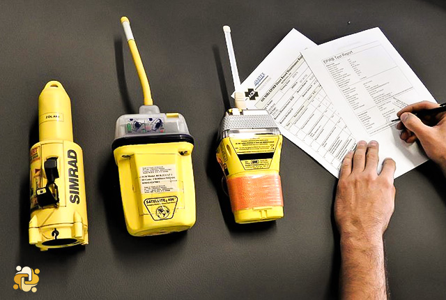
Note: The Maritime Mobile Service Identity (MMSI) number stipulated in the radio license should be coded into the DSC equipment, and if appropriate into the satellite EPIRB. If the national authority accepts serial number or call sign for identification of satellite EPIRB’s, the correct serial number or call sign must be coded into the satellite EPIRB.
References:
- SOLAS
- Maritime and Coastguard Agency Guidelines

Admin
Related Articles

Emergency Position Indicating Radio Beacon (EPIRB)
2023-12-30 14:12
Radio personnel requirements
2022-12-28 21:12
Routine test of radio equipment
2022-11-30 11:11