
Electronic Inclinometer - New SOLAS Requirement

Introduction
The 107th session of the Maritime Safety Committee was held from 31 May to 9 June 2023. In this regard, Committee adopted the proposed amendments to chapter V of the 1974 SOLAS Convention, in relation carriage of electronic inclinometer. This amendment should be deemed to have been accepted on 1 July 2025 and enter into force on 1 January 2026.
What’s New?
Refer to adopted amendment on MSC 107, container ships and bulk carriers of 3,000 gross tonnage and upwards constructed on or after 1 January 2026 shall be fitted with an electronic inclinometer, or other means, to determine, display and record the ships roll motion.
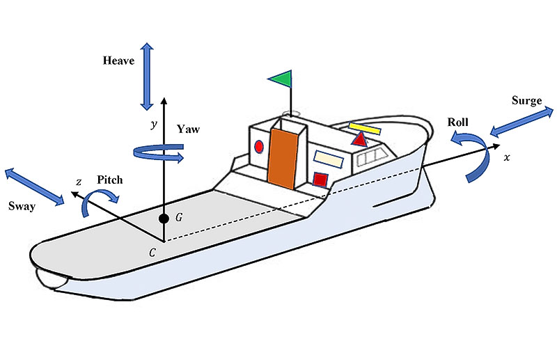
Figure 1 – Ship’s Motions
Electronic Inclinometers are instruments for measuring angles of slope and inclination of an object with respect to its gravity by creating an artificial horizon. It is also known as a tilt sensor, tilt indicator, slope meter, slope gauge, gradient meter, gradiometer, level gauge & level meter.
How Does It Work?
An inclinometer is commonly used in different industries like Aviation, civil engineering, Government, Marine, Military, and Transportation for platform leveling, boom angle indication, and slope angle measurement. The tilt angle range is the range of desired linear output measured in degrees. Important specifications to consider when searching for tilt sensors and inclinometers are the tilt angle range and number of axes.
The electronic inclinometer sensors are gravity based with no moving parts and nothing to break – very reliable for rugged applications.
Inclinometers measure the orientation angle of an object with respect to the force of gravity. This is done by means of an accelerometer, which monitors the effect of gravity on a tiny mass suspended in an elastic support structure. When the device tilts, this mass will move slightly, causing a change of capacitance between the mass and the supporting structure. The tilt angle is calculated from the measured capacitances.
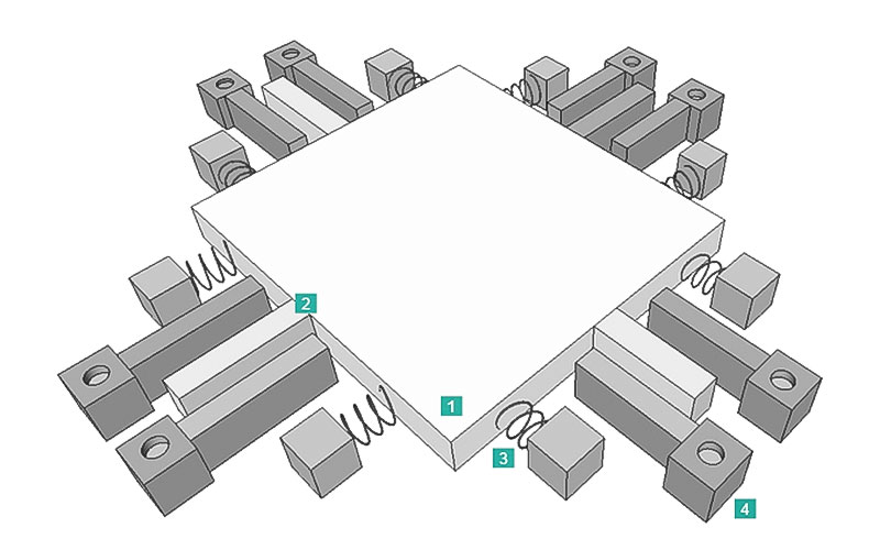
Fig. 2: Principle of a MEMS sensor
1- proof mass with, 2- electrodes, 3- springs, 4- fixed electrodes
The function can be illustrated with a simplified model with two electrodes: one fixed, and the other (the proof mass) is movable, suspended by spring elements (see Fig. 2). When the inclinometer is in a horizontal position (Fig. 3.1), the capacitance between the electrodes is measured. If the sensor is tilted (Fig. 3.2), the movable mass and its electrode will change position relative to the fixed electrode. This resulting change of capacitance between the two electrodes is measured by the sensor cell and used to calculate the new inclination value.
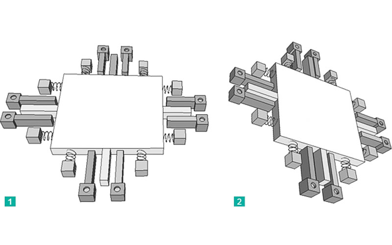
Fig. 3: Position of a MEMS sensor
1 MEMS sensor in horizontal position, 2 MEMS sensor in tilted position
This working principle has been proven in many industrial and commercial applications, such as mobile phone motion sensors and car airbags. These consumer applications usually require low grade accelerometer cells which typically deliver accuracies of less than 1 degree.
Pursuant to above mentioned requirements for some ship types, in the following, we discuss the performance standard of the electronic inclinometer in marine industries.
Performance Standards for Electronic Inclinometers (Resolution MSC.363 (92))
Electronic inclinometers are intended to support the decision-making process on board in order to avoid dangerous situations as well as assist in and facilitate maritime casualty investigations by providing information about the roll period and the heel angle of the ship.
Electronic inclinometers should, in a reliable form:
- determine the actual heel angle with the required accuracy;
- determine the roll amplitude with the required accuracy;
- determine the roll period with the required accuracy;
- present the information on a bridge display; and
- provide a standardized interface to instantaneous heel angle to the voyage data recorder (VDR).
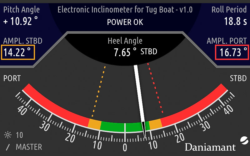
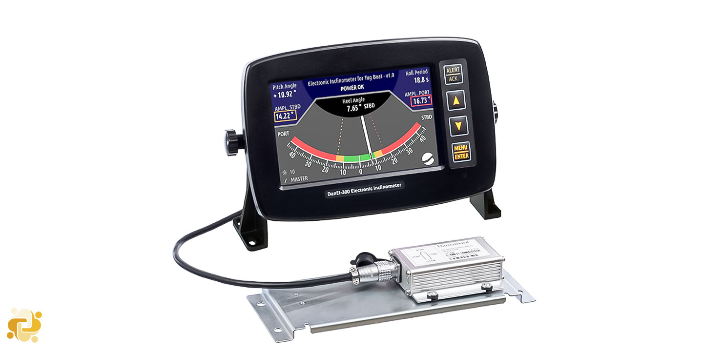
Figure 4 - Electronic inclinometers display
In addition to the general requirements set out in the General requirements for shipborne radio equipment forming part of the Global Maritime Distress and Safety System (GMDSS) and for electronic navigation aids (resolution A.694(17)) and the presentation requirements set out in the Performance standards for the presentation of navigation-related information on shipborne navigational displays (resolution MSC.191(79)), electronic inclinometers should meet the requirements of these standards and follow the relevant guidelines on ergonomic principles adopted by the Organization.
Module A – Sensor
Electronic inclinometers should be capable of measuring the actual heel angle and determining the amplitude of the rolling oscillation of the ship over a range of ± 90 degrees. Actual heel angle is the momentary angle of roll referenced to a levelled ship to port or starboard side.
Electronic inclinometers should be capable of measuring the time between the maximum values of the rolling oscillation and determining the roll period over a minimum range of 4 to 40 s. Roll period is the time between two successive maximum values of heel angle on the same side of the ship.
Electronic inclinometers should provide the data with sufficient accuracy for a proper assessment of the ship's dynamic situation. Minimum accuracy of the measurements should be 5 per cent of reading or ± 1 degree, whichever is the greater for angle measurements and 5 per cent of reading or ± 1 s, whichever is the greater for time measurements.
Actual heel angle and time measurement accuracy should not be unduly affected by other linear or rotational movements of the ship (e.g. surging, swaying, heaving, pitching and yawing) or by transverse acceleration ranging from -0.8 g to +0.8 g.
Module B – Operational and Functional Requirements
Electronic inclinometers should display:
- the roll period with a minimum resolution of 1 s; and
- the roll amplitude to both port and starboard side with a minimum resolution of 1 degree.
The actual heel angle to port or starboard should be indicated in an analogue form between the limits of ± 45 degrees.
The display may be implemented as a dedicated display or integrated into other bridge systems.
Electronic inclinometers may optionally provide a warning for indicating that a set heel angle had been exceeded.
The device should internally check and indicate to the user if all components are operative and if the information provided is valid or not
Module C – Interfacing and Integration
Electronic inclinometers should comprise a digital interface providing actual heel angle information to other systems like, e.g. VDR, with an update rate of at least 5 Hz. Electronic inclinometers should also comprise a digital interface providing the displayed information of roll period and roll amplitude. Roll amplitude is the maximum values of heel angle to port or starboard side.
Electronic inclinometers should have a bidirectional interface to facilitate communication, to transfer alerts from inclinometers to external systems and to acknowledge and silence alerts from external systems.
The digital interface should comply with the relevant international standards. (Refer to standard IEC 61162 [Maritime navigation and radio-communication equipment and systems – Digital] interfaces)
The installation position of the sensors of the electronic inclinometer should be recorded and made available for the configuration of the VDR.
Electronic inclinometers should be powered from the ship's main source of electrical energy. In addition, it should be possible to operate the electronic inclinometers from the ship's emergency source of electrical energy.
Related Articles


Emergency Position Indicating Radio Beacon (EPIRB)
Emergency Position Indicating Radio Beacons (EPIRBs) play a crucial role in maritime safety by facilitating rapid distress signal response. Regulation 14.1 of the International Convention for the Safely of Life at Sea (SOLAS), 1974, as amended, concerning radio-communications for the Global Maritime Distress and Safety System (GMDSS), which require, inter alia, that all radio equipment shall conform to appropriate performance standards not inferior to those adopted by the Organization.